Refit Project Update - Q4 2022
The last two months have been full of activity and progress! Having Escargot on the water for nearly six weeks was an invaluable experience, …
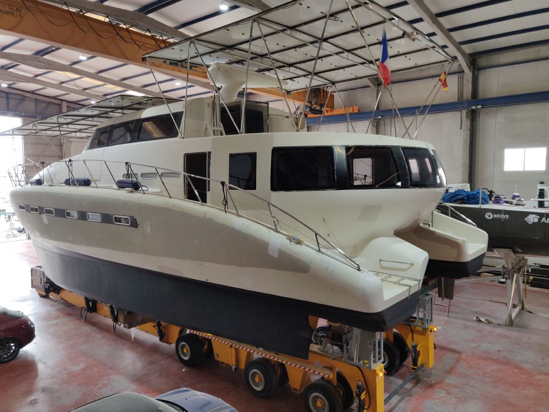
The last three months have been very productive. We’ve made significant progress, giving the boat a fresh new look and integrating crucial systems such as 220VAC inverters, a NMEA2000 network, and a dedicated cockpit navigation system. A new cooktop has also found its place at the salon bar. All these exciting projects remain on track for our planned launch date of May 15th.
However, a pressing concern has emerged regarding recurring issues with our 96VDC battery bank. These challenges could potentially delay our launch if not resolved in the coming weeks.
Giving Escargot a clean, refreshed appearance was a key goal for this quarter. We began by preparing the flybridge instrument panel, filling unused holes with plywood and epoxy filler to create a smooth surface for painting.


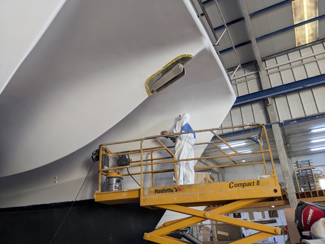
Next, we applied two coats of International One Up primer, ensuring a strong foundation for the topcoats.

Following the primer, two coats of Toplack Plus were applied, with careful masking to preserve the areas designated for anti-slip paint.

Finally, we applied two coats of International Interdeck anti-slip paint, ensuring both aesthetics and safety on the flybridge, the sundeck, and the side decks.

For charging our 12VDC and 24VDC banks from the main 96VDC energy storage, we opted for MPPT chargers over simpler DC-DC converters. A critical technical requirement, specified in the documentation for most MPPT chargers, is that the battery (low voltage) side of the charger must always be connected before the solar (high voltage) input. In our specific setup, this means we must always connect the 12VDC or 24VDC bank before connecting the 96VDC supply to the “solar input” of our EPEVER XTRA 3415N XDS2 chargers.

Unfortunately, we gained firsthand experience with this technical requirement while working on the 24VDC house bank. We inadvertently forgot to disconnect the 96VDC supply before briefly disconnecting the 24VDC side. The MPPT charger promptly generated a puff of smoke, illustrating the importance of the specified connection sequence.

Given that the main board utilizes surface mount technology, repairing the burnt components will be complex. This damaged EPEVER charger will be kept for spare parts, and we’ve learned a valuable lesson: always disconnect the 96VDC supply before performing any work on the low voltage battery banks!

We have completed the electrical connections of our two inverters to their DC breakers on the 96VDC busbar. The 8Kw SNADI inverter will serve as our primary daytime power source, while a smaller 3.5kW peak model is dedicated for nighttime use or as a backup.

Our forward cockpit navigation computer is a repurposed Samsung Chromebox running Ubuntu Linux. Both the Chromebox and its 19" LCD display operate on AC power ranging from 100V to 240V. Interestingly, due to their switching power supplies, these devices can also be powered directly from our 96VDC battery bank, as the nominal voltage exceeds 100VDC.
We installed a DC double breaker connected to the 96VDC busbars and ran a dedicated power line to an electrical box located under the cockpit for these equipments.

We built a plywood cover plate to securely hold the computer on the navigation panel.

While the wooden panels for holding the monitor and computer still require varnishing, the navigation computer is now mechanically and electrically installed.

We installed a NMEA2000 bus running from the bottom of the port side hull where our depth-speed-temperature sensor is, to the forward cockpit to receive the 12VDC injection and possible future devices, and to the aft flybridge to connect with the Raymarine Axiom chart plotter and the Amec AIS transponder. The final step involves cutting the opening on the flydeck instrument panel for the external chart plotter mounting.

We’ve begun the process of running 220VAC wiring for several key circuits around the boat. This includes dedicated outlets for the salon fridge, the bar cooktop, and provisions for a potential air conditioner, should we decide to install one in the future.


Our 96VDC battery bank, installed just over a year ago, has yet to be working as expected. To keep the high voltage battery bank always charged while in the shipyard warehouse, we use a battery charger connected to the building main power. This charger is controlled via the CAN bus of the Battery Management System (BMS).
The BMS is designed to balance individual cells, ensuring they maintain similar voltages. However, we’ve observed a gradual voltage drift over time. When the battery reaches full charge, the BMS initiates its balancing process, shunting cells with the highest voltage to allow others to continue charging. Unfortunately, within approximately a minute of balancing, a “cell temperature too high” error appears on the BMS, causing the charger to stop and the balancing process to terminate prematurely.

This has been going on for months, and despite ongoing communication with our battery manufacturer, we have been unable to resolve it. We finally decided to open one of the aluminum battery box to investigate the cause of this “high temperature” error. Inside, we discovered two 3D-printed plastic boxes mounted directly on top of the CATL 96VDC NMC batteries.

Inside these 3D-printed boxes, we found printed circuit boards (PCBs) that are typically desiged to be screwed directly to prismatic cell terminals. Each of these PCBs contains an SMT temperature sensor, intended to measure the temperature of a cell terminal. However, within the plastic boxes, the sensor appears to be measuring the PCB’s temperature instead. This PCB heats up significantly when current flows through the cell balancing shunt. This setup strongly suggests a significant design flaw that prevents the BMS from performing its cell balancing function, which will only increase cell voltage drift over time.

In addition to that, we were surprised to find that the power cables exiting the battery’s aluminum boxes connect directly from the battery’s positive and negative bars. They are not routed through an electronic board or a contactor controlled by the BMS, which would typically be responsible for cutting charge or discharge in the event of critical thermal issues, low/high voltage limits, or other safety situations detected by the BMS.
We have initiated further discussions with our battery integrator to fully understand how this system is intended to operate. Based on our observations, this configuration does not appear to meet standard safety protocols for lithium batteries in mobile applications. These findings are making us uncomfortable and concerned. This critical issue must be resolved before Escargot returns to the water in the next month or two.
The last two months have been full of activity and progress! Having Escargot on the water for nearly six weeks was an invaluable experience, …
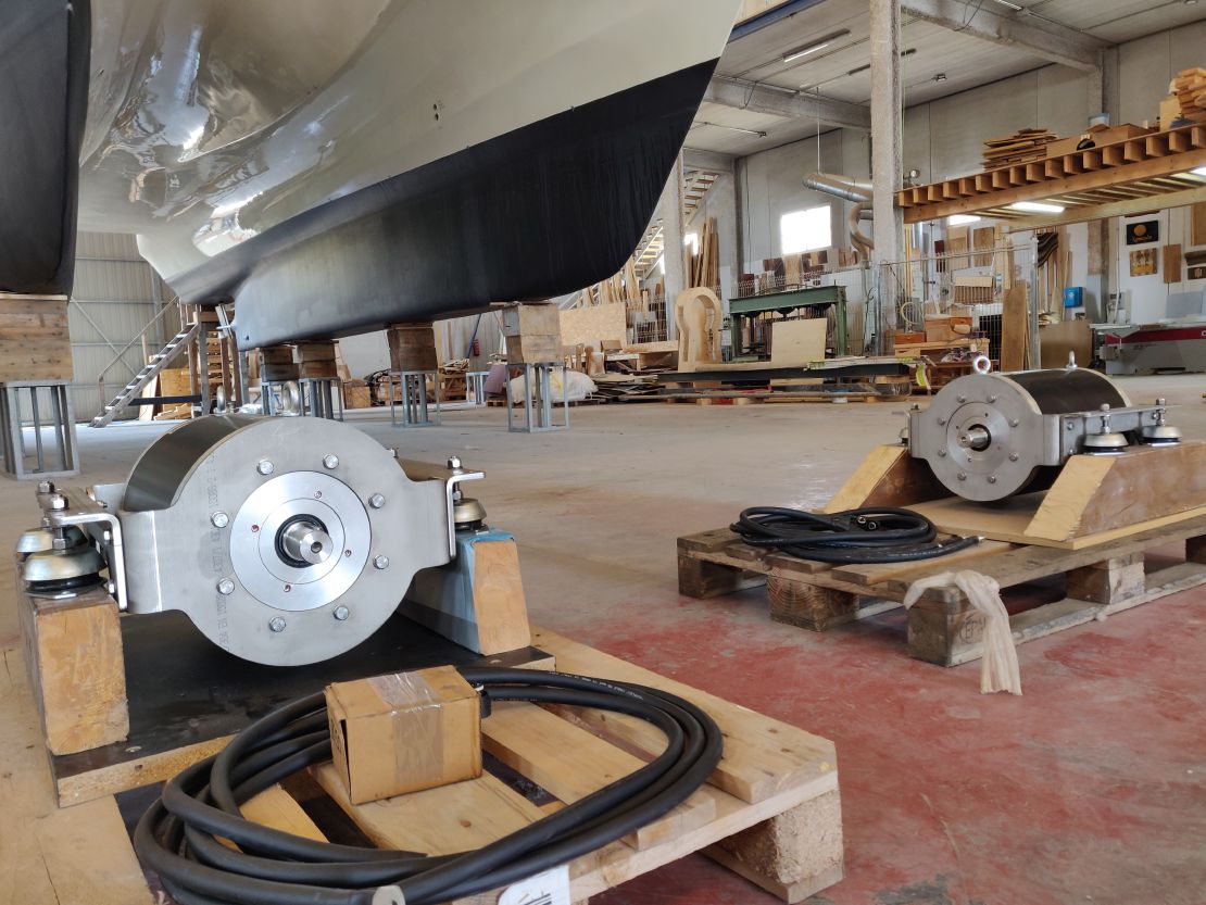
The third quarter of 2022 was a period of significant progress on our vessel's refit. With the arrival of our new FIMEA N80L motors at the end of …